About this module
-
Prerequisites:
-
Objectives: This module is an introduction to the essential material of CISP310. Specifically, this module connects the elemental logical constructs like disjunction, conjunction, and negation to physical devices like transistors.
Physical states
Physical devices
It makes sense to start with devices that are physical. These devices are/were used to implement computers at one point of time or another.
Electro-mechanical
An electro-mechanical device is one that uses electricity to actuate/move contacts physically (mechanically). A motor drives a rotor. On each rotor are contact points at different rotational positions. The rotor then connects different electrical contact points on the stator.
An electromechanical computer is extremely bulky due to the use of rotors, plug boards, and motors. The use of motors (to change state by changing the rotational state of rotors) is also very slow compared to other mechanisms. However, given the right circumstances, an electromechanical computer can be worthwhile.
At the end of World War 2, German Enigma encryption machines received a fourth wheel to scramble broadcast communication. This made the previous manual deciphering method no longer effective. The bombe computer was devised to semi-automate the deciphering process. Despite being one of the slowest mechanisms, the electromechanical bombe proved to be effective against the Enigma encryption machines.
Vacuum tubes
A is, as the name implies, a glass tube that is mostly vacuum inside. At the center of a vacuum tube is a heating element that is not unlike the filament of an incandescent light bulb. The heating element heats the next layer, which is known as the cathode. The cathode must be sufficiently heated for electrons to become mobile.
Depending on the device, there is at least one but potentially more layers outside the cathode. For our discussion, a has two layers outside the cathode. The immediate next layer is a mesh-like gate, and the outermost layer is a solid plate anode.
The main idea is that a triode vacuum tube is a valve. The heating element should always be on because that is how the cathode works. A negative electrical potential (voltage) is applied to the cathode. A positive electrical potential is applied to the anode.
In the absence of a gate or no voltage at the gate, electrons are emitted from the cathode and go to the anode. As a result, there is electrical current.
However, by using a relatively low negative voltage at the gate, the current passing through can be reduced. The voltage difference between the cathode and anode is in the order of 100V, while the gate voltage is in the order of 1V.
Essentially, a triode is a non-mechanical and non-hydraulic valve. The key concept, however, is that the control mechanism of the valve uses the same physics (electrical) as the quantity being controlled.
Bulky, hot, energy-consuming vacuum tubes are components that make rather large computers. Furthermore, due to the large surface areas of the cathode and anode, vacuum tubes are also relatively slow devices. Nonetheless, computers made from vacuum tubes have no moving mechanical components, and thus, a significant improvement in terms of reliability and speed.
Although there were computers before the Colossus, the Colossus is one of the most recognized vacuum tube computers due to its role at the end of World War 2. The Colossus was invented to decipher messages encoded by. The Lorenz cipher is considerably more complex (and expensive) compared to the Enigma machines. As such, the Lorenz cipher was only used for “ultra” secret communication. But this also made it a high-priority target to crack.
Transistors
A transistor is a general term for devices that make use of semiconductor material. A semiconductor material is actually a non-conducting material with other elements. For example, Silicon (Si) does not conduct electricity. However, when elements like boron and phosphorus are present, the material conducts due to the charged carrier (either as holes or electrons).
The term semiconductor implies the material can conduct or not conduct. This is due to the most basic semiconductor construct, the PN junction. A PN junction allows the flow of current in only one direction.
A transistor is a mechanism that is based on the simple PN junction. The physics is a bit beyond the scope of this module. From the external perspective, however, a transistor is like a vacuum tube. A small signal can be used to control a valve that switches the flow of a much bigger signal. In this case, both the control signal and the signal being controlled are electrical.
Even the original transistors are a bit smaller than vacuum tubes in size. Furthermore, because there is no need to encourage electrons to fly through a vacuum, the operating electrical potentials of transistors are considerably less than those of vacuum tubes.
As a result, computers made from transistors are much smaller than those made from vacuum tubes, require far less energy and operate faster as well.
There are several revolutions in terms of transistor technologies. For this module, there will be no discussion of the various types of transistor or the packaging of transistors.
Physical states
Regardless of the physical mechanism, all types of computer components have “states”. Since we are focusing on digital and binary computers, components are only in one of two states. Because almost all devices used to make computers can be seen as valves, we can see the state of a device as allowing flow (closed) or not allowing flow (open).
Likewise, we can also measure physical quantities as the outputs of devices. For electronic or electro-mechanical devices, this often means measuring the electrical potential of an electrical contact point. Again, because our focus is on digital and binary computers, the electrical potential is either high or low.
There is nothing mysterious about physical devices, their actual states or their observable states. After all, it is all physics!
Truth
Computer science is not a science because it has nothing to do with the truth (of nature). Instead, it is a study of the implications of artificial rules regarding truth values.
How does this relate to physical devices and physical states? Easy! Since a device has two states (either observable, like voltage, or actual like allowing flow), it is understandable that we can assign truth values to the states. For example, we can arbitrarily assign “true” to a high voltage and “false” to a low voltage. There are times when the truth assignment is reversed.
But what does this buy us? There is nothing to gain by randomly labeling truth values to physical states. However, what if we can design circuitry so that it mimics logical operations?
Let’s see how this works.
Transistor types
Not going into the specifics, let us discuss how to use two types of transistors. Note that there is an alternative description of transistors in the Logisim. Go to Help | Library Reference | Transistor.
The first type is the more intuitive type. We will call this an N transistors. In real circuits, an N transistor can be a BJT (bipolar junction transistor) or a MOSFET (metal oxide semiconductor field effect transistor). Regardless of the type, a high voltage control signal turns on the valve to allow flow, and a low voltage control signal turns off the valve to stop flow.

For an N-transistor, the arrow goes from low voltage to high voltage, while the pin perpendicular to the direction of the arrow is the gate (control signal). Unlike a general-purpose valve, an N-transistor only lets flow from low voltage to high voltage.
The second type has a negated control signal, meaning a low voltage turns on the valve and a high voltage turns off the valve. This type of transistor is a P transistor. Again, A P transistor can be a BJT or a MOSFET. In the diagram of a P-transistor, the arrow has to go from high voltage to low voltage. The bubble indicates that the control signal is negated, where a low voltage at the gate enables flow from high voltage to low voltage.

To clarify a potential confusion, in both N and P transistors, the arrow indicates the flow from the “source” to the “drain”. However, in the case of an N transistor, the source is a low voltage (ground), whereas a P transistor has the high voltage (usually called “power” or VCC) as source. The gate is the control signal to allow or block flow. A bubble in a circuit schematic usually indicates negation.
A 2N2P circuit
Now let us analyze the circuit in figure 1{reference-type=”ref” reference=”fig:nand2”}.
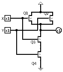
First of all, a solid dot means there is a connection at a junction. Otherwise, if two wires cross without a solid dot, the wires are not connected. The input pins are square, indicating the voltage is to be specified by something else. The single output pin is circular, indicating the voltage is the result of whatever connects to it.
There are four transistors, Q1 to Q4, in this circuit. Note how Q1 and Q2 are P transistors, while Q3 and Q4 are N transistors. Furthermore, the gates of Q1 and Q3 are connected to input X, while the gates of Q2 and Q4 is connected to input Y.
Instead of actually quantifying X and Y in voltages, let’s just assign a value of 1 to a high voltage and a value of 0 to a low voltage. The same applies to the output and all the other “nodes” of this circuit. A “node” is a term that refers to all the wires that are electrically connected and, therefore, logically the same conductor.
First of all, see how the arrows of Q1 and Q2 are in opposite directions from those of Q3 and Q4? This is not a mistake. This is because in the case of a P transistor, the “source” is the high voltage end, whereas in the case of an N transistor, the “source” is the low voltage end. Also, note the bubble that is at the gate pin of Q1 and Q2. This signifies that the input is negated, when the input is a 0, the transistor is turned on (allowing electrical current through).
Now our task is to figure out the state of the output pin (the circular object all the way to the right) depending on the inputs X and Y.
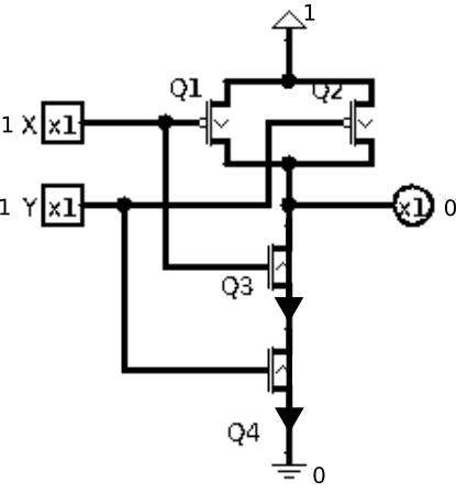
In the first case, let X and Y both be zeroes. This turns on both Q1 and Q2, connecting the output pin to the high voltage source. There is no path to connect to the low-voltage source because Q3 and Q4 are both disabled (not connecting). This is illustrated in figure 2{reference-type=”ref” reference=”fig:2n2p00”}.

In the second case, let X and Y both be ones. This turns off both Q1 and Q2 so that the output is no longer connected to the high voltage source. However, Q3 and Q4 are turned on, completing a path from the output pin to the low voltage source. This is illustrated by figure 3.
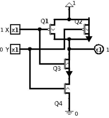
The last two cases are symmetric where one input is 1 and the other one is 0. We will illustrate the one where X is 1 and Y is 0. In this case, Q1 is off, Q2 is on, Q3 is on and Q4 is off. Because Q1 and Q2 are in parallel, having at least one connecting means the output connects to the high voltage source (via Q2 in this case). On the other hand, Q3 and Q4 are in series, both need to connect to complete a path to the low voltage source. Since only Q3 is connecting but Q4 is not connecting, there is no path to connect the output pin to the low voltage source. As a result, the output pin has a high voltage. This is illustrated in figure 4
From transistors to logic gate
This is one of the key “ah-ha” moments of this modules. At this point, the circuitry previous analyzed can now be considered a logic gate. This is a rather important transition.
The circuitry that is made of 2 N-transistors and 2 P-transistors is a physical thing that has known physical properties. However, I now claim that this circuitry mimics/implements the behavior of a logical construct. But which logic operator is this?
Let us first example the behavior of the circuit using a table.
| X | Y | output |
|---|---|---|
| 0 | 0 | 1 |
| 1 | 1 | 0 |
| 1 | 0 | 1 |
| 0 | 1 | 1 |
At first glance, because there are three 1’s and one 0, we may think this is disjunction (or). But it is not! You can see that the output is 1 whenever at least one input is a 0 (instead of a 1 in the case of disjunction). As it turns out this logical operator is a seemingly weird one called a negated-and, often abbreviated to nand.
If we denote the output as W, then W=!(X && Y) in C/C++ syntax, or
$W=\neg(X \wedge Y)$ in math symbols, or $W=\overline{X\cdot Y}$ in
computer engineering notation, or $W=\overline{XY}$ in abbreviated
computer engineering notation, or simply W=not(X and Y) using plain
text.
Nand is all we need!
Some may be thinking what practical use does nand as operator has. Well, it is actually the only operator that we need! Let us examine how nand can be used to “emulate” all the common logic operators that we have learned.
The nand operator is sometimes denoted as $\uparrow$.
not
This one is easy, but it is also a little tricky:
$\neg X = X \uparrow X$
Note that the negation of $X$ can also be denoted as !X in C++ syntax,
or $\overline{X}$ in computer engineering notation, or /X in
electrical engineering notation.
and
Once we have negation, the negation of nand is and:
$X \wedge Y = (X \uparrow Y) \uparrow (X \uparrow Y)$
Note that the conjunction of $X$ and $Y$ can also be denoted as X && Y
in C++, or $X \cdot Y$ in computer engineering notation, or $XY$ is
abbreviated computer engineering notation.
or
Or is a little tricky because we have to use De Morgan’s law in this case.
$X \vee Y = \neg(\neg(X \vee Y)) = \neg((\neg X \wedge \neg Y)) = \neg X \uparrow \neg Y = (X \uparrow X) \uparrow (Y \uparrow Y)$
Note that the disjunction of $X$ and $Y$ can also be denoted as X || Y
in C++, or $X+Y$ in computer engineering notation.
Oh, really?
You can use truth tables to show validity of the nand emulation of all other commonly used gates. This is a good exercise to make sure your understanding of the nand gate is correct.
Numbers and values
In this module, we are only going to say this: a number is a representation of a value (quantity). Numbers are necessary so that people can mutually understand the concept of quantities so that trade and other quantity related activities can take place.
In other words, if you consider yourself (as a person) as a quantity, then your name is the number corresponding to that quantity. For those who have multiple names, all those names refer to the same person!
This implies that the same quantity may have different “names”, or numbers corresponding to it. We will explore this in another module.
At this point, let us just consider the translation from voltages to numbers: a high voltage represents 1, and a low voltage represents 0.